CBMS
Overview
CBMS stands for Crappy Battery Monitoring System. CBMS is a no-frills battery monitoring/protection system in that it aims to be as minimal as possible, favoring simplicity and safety functionality over performance. CBMS was originally designed to be easily retrofitted into an existing battery pack. A big design goal was to minimize harnessing and maximize spatial locality. In practice it takes about two days to assemble, test and install.
I prefer the acronym BMS for consistency with automotive terminology, so for the sake of this document I'll stick with it. This term can be used interchangeably with BPS (Battery Protection System) which is the typical term used by the North American Solar Challenge.
History
CBMS has its roots in a BMS I designed as a contingency for the 2011 U-M solar car, Quantum. That system consisted of battery powered sense nodes centrally wired to a master board. Although that system worked, it was a bit unwieldy due to the complexity of the master. Luckily we were able to debug the team's existing BMS and the contingency was unused.
In 2014 I was invited to race Quantum in the Abu Dhabi Solar Challenge. With about a month and a half to prepare, I decided to design, build and test CBMS once again as a contingency. On Christmas Day we got the bad news that Quantum had to be air shipped, which meant dismantling the battery pack, and CBMS got promoted to prime-time.
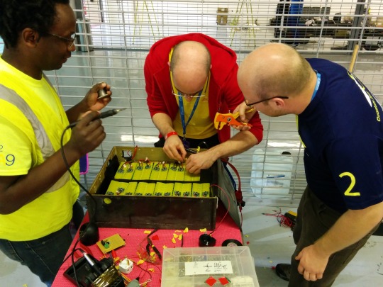 CBMS integrated smoothly into Quantum, but the really interesting story is how it ended up in another team's battery pack. When some guys from Principia heard that a Japanese middle school team was missing a BMS, they headed over to our pit lane and asked if we had any ideas. I pulled out an unpopulated PCB panel and my box of components, and Principia started soldering away! It took some creative on-the-spot engineering, but over the next day we were able to install and test CBMS in the Japanese car.
Design
Open Source Hardware
In the interest of giving back to the solar car racing community, I encourage others to learn from and build on the CBMS design. Feel free to use and modify without restriction. I only ask that you drop me a line if you find this information useful. If you happen to commercially apply any of these concepts that's cool too, but you should feel obligated to sponsor the U-M solar car team and at the very least buy me a beer!
Support
I'm happy to respond to questions, participate in reviews, brainstorm new features, etc. It's personally rewarding and lots of fun collaborating and mentoring. My free-time is limited, though, and I can't promise anything beyond reasonable e-mail correspondance. If you are looking for more of a turn-key BMS solution, I'll gladly entertain business proposals.
Overview
CBMS consists of two types of components: Node and Master. There is a node for each battery module, and one master for the entire pack. The nodes are responsible for measuring module voltage and temperature, while the master is responsible for measuring pack current and controlling the pack contactor. The master and nodes communicate between each other using a simple UART protocol.
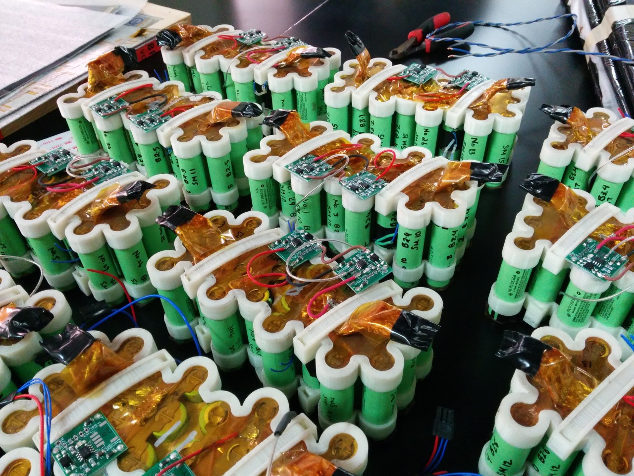
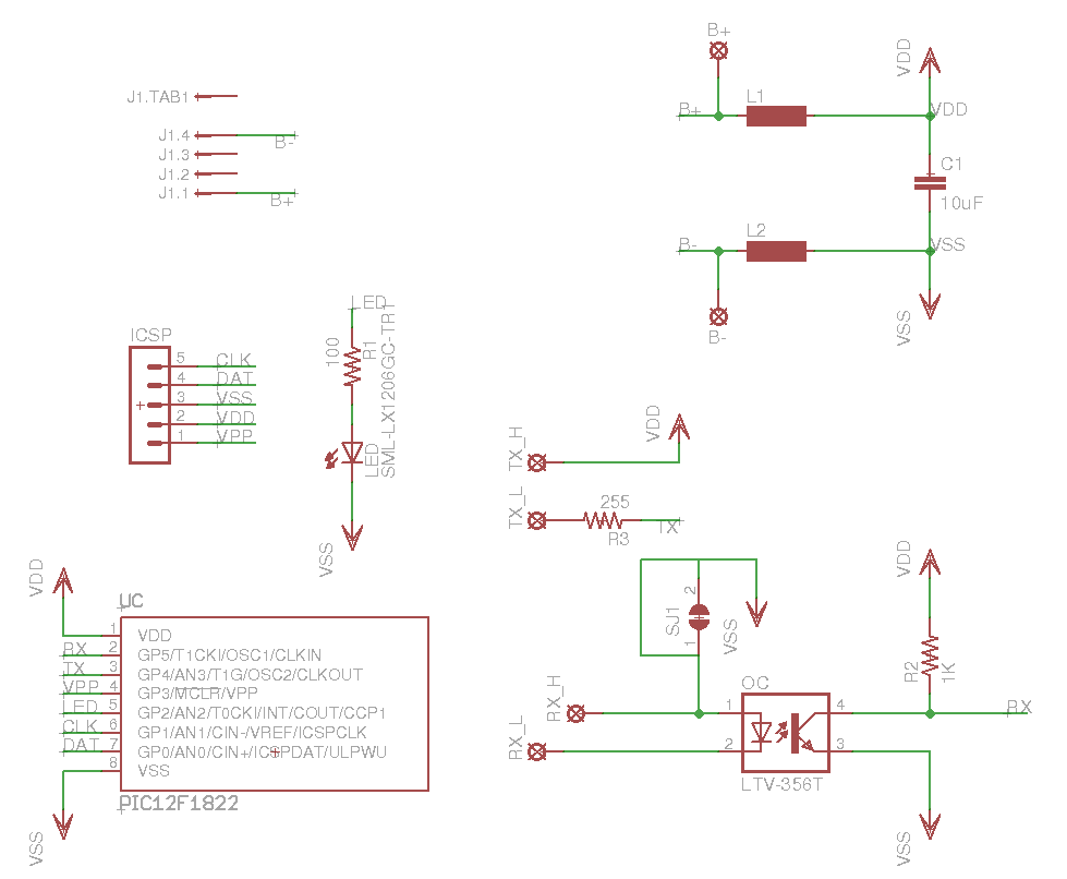
Node
Each node fundamentally consists of a low power microcontroller, an optocoupler, and a handful of passive components. The chosen microcontroller includes a built in voltage reference and temperature junction, allowing voltage and temperature to be measured without any additional components. By making use of the microcontroller's sleep mode, the node is able to be powered directly off of the module sense leads.
Nodes are daisy chained together and communication is actively repeated from one node to the next. The optocoupler allows each node to communicate with the next node in sequence regardless of common mode voltage.
A node sits in a low power sleep mode until a communication packet comes in. The node wakes up, receives the packet, takes its samples, and sends out a modified packet.
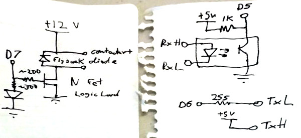
Master
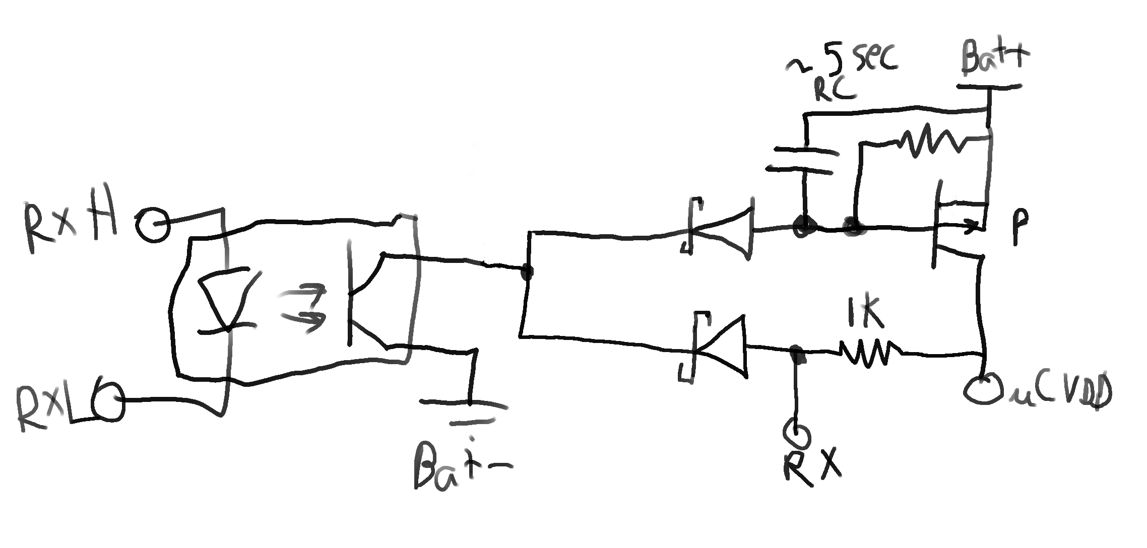
The master consists of a microcontroller, an optocoupler, a current sense circuit, and a contactor driver. The master transmits to the first node by driving the node's optocoupler and it receives from the last node which drives the master's optocoupler.
Communication
Due to the typical slowness of optocouplers across a reasonable operating temperature range, CBMS communicates at a very slow baudrate of 4800 baud. Since the nodes are daisy chained together and data is sequentially communicated through all nodes, it is important to keep the packet size small to keep overall system latency reasonable. Therefore, instead of communicating every module's voltage and temperature in each packet, the module samples are decimated into minimum, maximum and sum voltages and temperatures.
It is important to ensure data integrity whenever communicating over a boundary such as between two microcontrollers, especially when the data being communicated is used for control. There are many ways to do this such as outlier detection or frame check sequences. In the case of CBMS, I decided to use an FCS in the form of the entire packet's bitwise complement. Although this is rather wasteful in terms of communication bandwidth, it has one benefit: the overall duty cycle of the entire packet + FCS waveform is consistent regardless of packet content. Inter-node communication is by far the largest energy drain, and since the nodes are powered off of the modules directly, maintaining a consistent duty cycle across all nodes minimizes module imbalance over time.
Future Improvements
Node
Hardware Shutdown
Currently, the nodes are always powered on and running software. When the system is inactive, they should be sleeping and drawing 50-100uA. For a large battery this is negligable, but over the course of months this can add up and cause pack imbalance. Also, as a software engineer I am paranoid that a software bug can result in improper current consumption and a ruined battery.
One idea would be to implement some sort of hardware shutdown that would electrically disconnect the microcontroller when the system is inactive for more than a few seconds.
This has the additional benefit of enabling more flexibility in microcontroller selection because things like external references and temperature sensors could be used without increasing quiescent current draw.